miniThrottle - Builders Notes
miniThrottle: A model railroad WiFi throttle.
Pin Assignments
These are defined in miniThrottle.h which can be copied from miniThrottle.h.example. When you update your project for source that should preserve any customisations you have made to miniThrottle.h. However, if you then encounter compiliation errors you may have to compare the two files and update your customised copy with any new or changed definitions.
The Esp32 is very flexible in how pins are assigned. But there are some limitations that need to be followed. The list in miniThrottle.h is a summary of these, please be aware of these before simply assigning a function to an I/O pin. Each I/O pin can only perform one function.
 **********  PIN ASSIGNMENTS  ******************************************************************
 *
 * NB: pins 34 and above are read only, do not use them for outputs, assign to switches and rotary encoders
 *     pins 34 and above do not have internal pull up resistors, if using for switches add your own 20K pull up
 *
 * NB: pins 06 to 11 are connected to the internal flash memory, do not use these even if available on your board
 *
 * ADC is used for Potentiometer throttle (Pot-Throt / POTTHROTPIN)
 *     ADC1_CH0 - GPIO 36
 *     ADC1_CH1 - GPIO 37
 *     ADC1_CH2 - GPIO 38
 *     ADC1_CH3 - GPIO 39
 *     ADC1_CH4 - GPIO 32
 *     ADC1_CH5 - GPIO 33
 *     ADC1_CH6 - GPIO 34
 *     ADC1_CH7 - GPIO 35
 * ADC2 not usable with WIFI enabled.
 *
 * DAC is used to drive 3v voltmeter speedo and brake pressure
 * DAC pins are limited to 25 and 26
 *
 * SPI bus can be mapped to other pins, but the "native" pins are
 * SPI  |    MOSI |    MISO |     CLK |      CS
 * VSPI | GPIO 23 | GPIO 19 | GPIO 18 | GPIO 05
 * HSPI | GPIO 13 | GPIO 12 | GPIO 14 | GPIO 15
 *
 * I2C bus can be mapped to other pins, but the "native" pins are
 *    SDA - GPIO 21
 *    SCL - GPIO 22
 *
 * The following are "strapping pins" which should in the state shown on reboot
 *    GPIO 05 (must be HIGH during boot)
 *    GPIO 12 (must be LOW during boot)
 *    GPIO 15 (must be HIGH during boot)
 *
 * Bringing the EN pin to GND temporarily will hard reset the ESP32 module
 *
Minimum build
One of the design objectives of miniThrottle was to minimise parts count to keep the build simple. The examples below show relatively simple builds using 2 main parts the Esp32 module, and either a keypad or rotary encoder. Some wiring is still required.
The examples below show the minimum builds which allow for a viable unit. The module used includes a built in SSD1306 display. This module uses pins 4 and 5 for I2C communications, which includes the display. I/O pins other than those shown in the "Configuration" sections below are commented out using a "//". This configuration section refers to the file "miniThrottle.h".
From version 0.5 onward miniThrottle gains the ability to relay WiThrottle to DCC-Ex. This required neith input (keypad/encoder) or display to work allowing it to replace a standard DCC-Ex WiFi module. However, with a display to will show additional information, and in some cases the DCC-Ex LCD display becomes redundant/optional! From version 0.5d, see miniThrottle.h.004 for a template file that will work as a "relay-only" on a module with built in SDD1306 display.
| Keypad only | Encoder only |
|---|---|

Parts List:
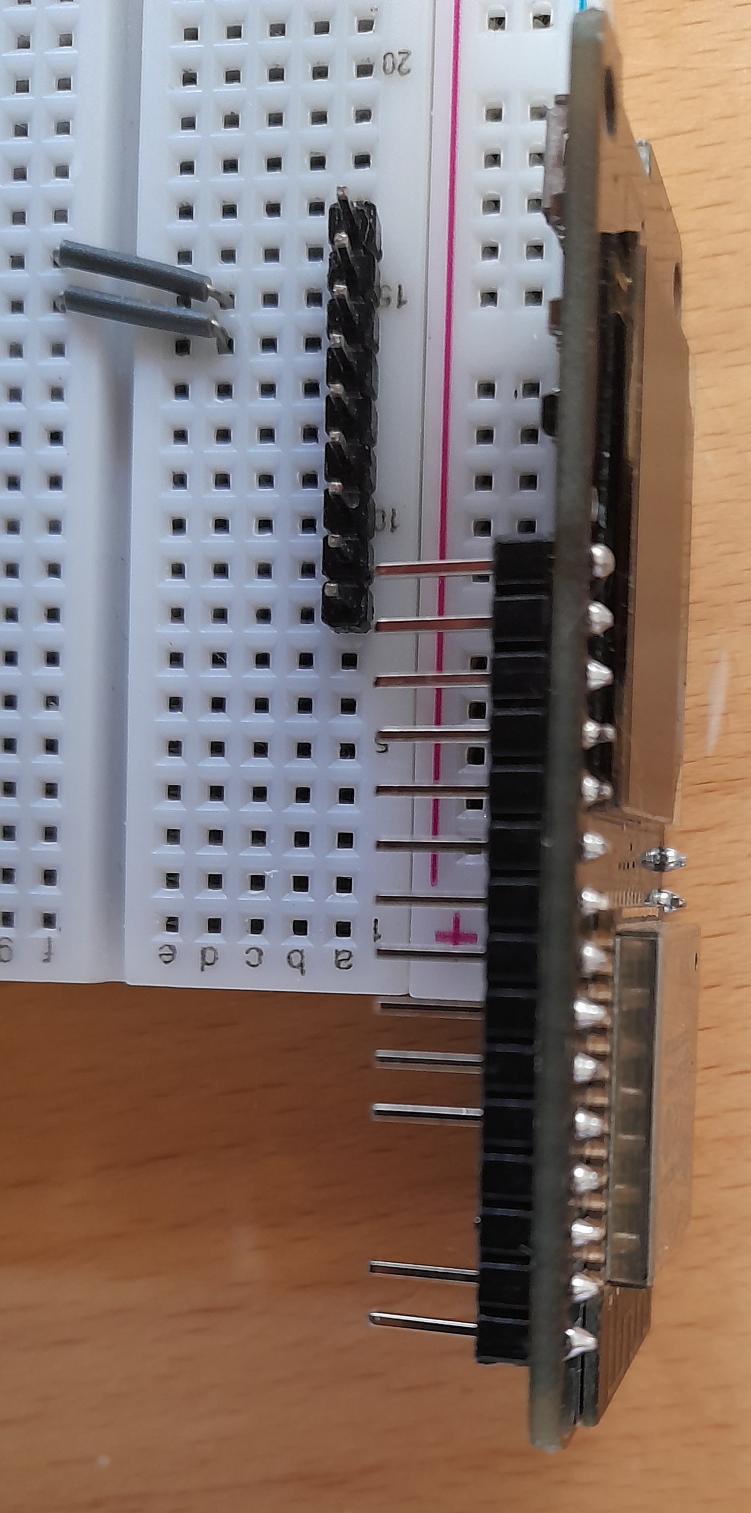
Notes: Since pins 4 and 5 are used for I2C commincations these are cut, and connections are made through spaces left from the opposite side of the board. (Pins 25 and 26) The keypad mapping of columns and rows is then just a sequential mapping of the pins exposed to the "right hand side" of the board. If only the header pins used are soldered to the module, the module should be supplied with sufficient pins as to connect to the keypad. However, using right angled header pins may be preferable in order to get the display closer to the edge of a case holding it. Configuration: #define SSD1306 #define key4x5 // Then within the section starting "#ifdef key4x5" #define MEMBR_COLS 16,25,26,00 #define MEMBR_ROWS 02,14,12,13,15 |
Parts List:
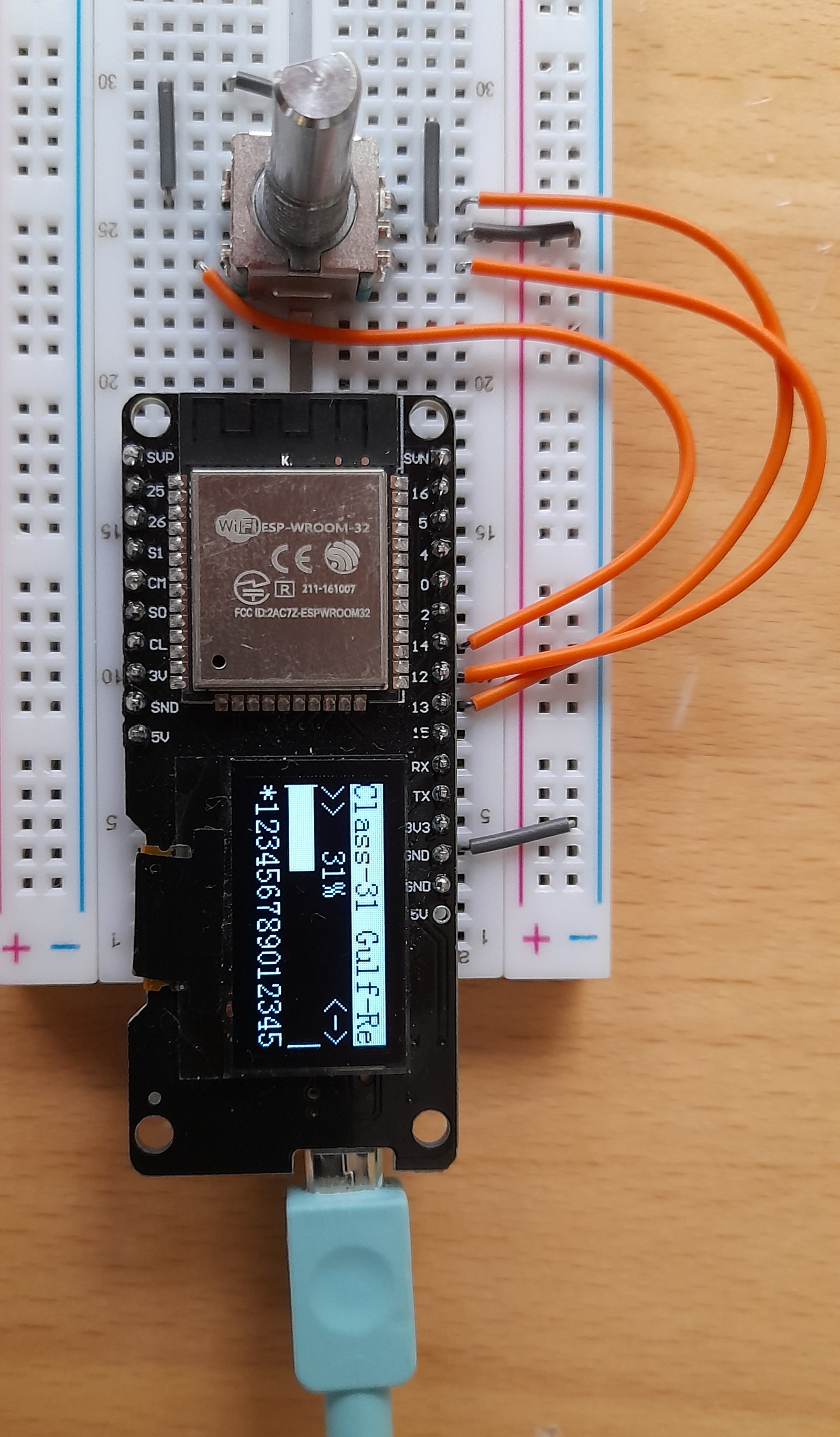
Notes: Since there is no mechanism to change direction of a controlled locomotive, it is recommended that "bidirectional" mode is selected as the default. Also note that since there are no numeric buttons, functions cannot be selected. As pin numbers below 34 are used for encoder connections, no additional pull up resistors are required. The middle pin of the encoder and one side of the switch are connected to ground. (GND or 0V pin) if the rotation goes the wrong way, simply switch the leads to pins 12 and 13. Configuration: #define SSD1306 #define keynone #define ENCODE_UP 12 // encoder up bounce #define ENCODE_DN 13 // encoder down bounce #define ENCODE_SW 14 // encoder switch |
| Encoder & Keypad | Relay with local control |


Parts List:
Notes: The option goes beyond the bare minimum required to operate miniThrottle, but is still a minimalist build. Since pins 4 and 5 are used for I2C communications these are cut, and connections are made through spaces left from the opposite side of the board. (Pins 25 and 26) Pins labeled SVP and SVN (pins 36 and 39 respectively) have a 20K pull up resistor connected to the 3.3V pins. The keys A, B, C, D may be mapped to produce U, D, L, R (up, down, left, right) to allow the keypad the select speed-up, speed-down and direction. Otherwise these functions can rely on the encoder to select, especially if left to run in bidirectional mode. Configuration: #define SSD1306 #define key4x4 #define ENCODE_UP 39 // encoder up bounce #define ENCODE_DN 16 // encoder down bounce #define ENCODE_SW 36 // encoder switch // Then within the section starting "#ifdef key4x4" #define MEMBR_COLS 02,00,26,25 #define MEMBR_ROWS 14,12,13,15 Version 0.5d onward: See miniThrottle.h.001 as template to copy to miniThrottle.h to replicate this design. |

Parts List:
Notes: This uses the same ESP32 module with built in SDD1306 display as other examples in this section. But relays to DCC-Ex while retaining a local control. This allows locomotive CVs to be queried and updated locally, while providiing a replacement option for the standard DCC-Ex WiFi option. Note the use of the 5K & 10K resistors to reduce the 5V output from DCC-Ex to tolerable voltages for the ESP32. The ESP32 transmit that connects to DCC-Ex is sufficiently high that it does not require a voltage boost, so a direct connection works OK. Configuration: #define SERIALCTRL 1 #define DCCRX 36 #define DCCTX 16 #define SSD1306 #define key4x4 #define POTTHROTPIN 39 // Then within the section starting "#ifdef key4x4" #define MEMBR_COLS 02,00,26,25 #define MEMBR_ROWS 14,12,13,15 Version 0.5d onward: See miniThrottle.h.003 as template to copy to miniThrottle.h to replicate this design. |
More Feature-Full Builds
Note: No parts lists are included for these, as they do no use prebuilt images, it is up to the builder to determine appropriate features and hardware to include.
| Handheld Build |
|---|


Notes: Includes 5V buck regulator and rectifier so can be charged from AC/DC 7-15V. ESP32 module includes battery charging circuitry. It uses a commercially available project box. Given interior space, it was reasonably tight to fit in all the components. Version 0.7 was used for the build and 12x24 font on the st7789 display gives a 20 character by 5 line display. Configuration: Hardware setup:
Reset = EN
SPI - Reset = 27
SPI - CS = 26
SPI - DC = 12
SPI - Clock/SCL = 14
SPI - Data/SDA = 13
Backlight = 16 (Rxd2)
Encoder Up = 25
Encoder Down = 33
Encoder Switch = 32
Trk Power LED = 22
Console - Tx = 1 (Txd)
Console - Rx = 3 (Rxd)
Keyboard Rows (4 rows) = 5, 15, 2, 0
Keyboard Cols (3 cols) = 18, 23, 19
A pre-compiled version is available. |
| All in one controller |


Notes: Includes 12V power adapter, and output of Main track, Prog Track and 12V DC. In photo, DCC-Ex and motor control hat are on top right of interior photo. miniThrottle and pot control in lower/middle left. The red button on the front panel is connected to reset. A st7735 display is used, and the miniThrottle build includes an encoder, track power LED and support for 20 key keypad. The cover and base of the case are linked using DuPont cables. Up to 8 WiFi clients are possible - total of simultaneous web and wiThrottle relay clients = 8. It listens for wiThrottle connections on port 12090 and relays these through a serial connection on ports 32 and 33. The standard serial port on USB remains available for disgnotics. Configuration: Hardware setup:
Reset = EN
DCC - Tx = 32
DCC - Rx = 33
SPI - Reset = 27
SPI - CS = 15
SPI - DC = 12
SPI - Clock/SCL = 14
SPI - Data/SDA = 13
Backlight = 22
Encoder Up = 39 (SensVN)
Encoder Down = 36 (SensVP)
Encoder Switch = 35
Trk Power LED = 26
Throttle Poten = 34
Console - Tx = 1 (Txd)
Console - Rx = 3 (Rxd)
Keyboard Rows (5 rows) = 17, 16, 4, 0, 2
Keyboard Cols (4 cols) = 19, 23, 18, 5
A pre-compiled version is available. |
| Thank you for visiting conferre.cf | Home |